A detailing layer is available in RISA-2D that lets the user set the "true" elevations and locations start/end, top of steel, etc...) for all members. For each member you can describe the connection point at member ends.
The areas where member detailing parameters can be added/viewed are:
Note:
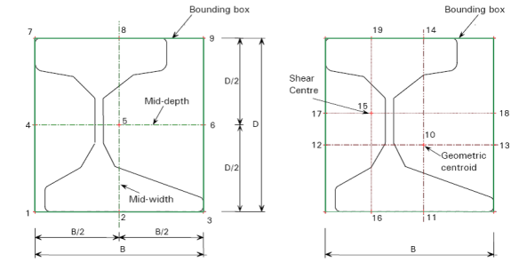
For each end of the member, both cardinal point positions and decimal local offsets are used to described the connection location. The location of the cardinal point is plotted as follows:
Figure 1: Cardinal point Location and Local Axis
| Cardinal point 1:lower left corner of the member section bounding box |
| Cardinal point 2:lower center point in the member section bounding box |
| Cardinal point 3:lower right corner of the member section bounding box |
| Cardinal point 4:mid-depth left point in the member section bounding box |
| Cardinal point 5:mid-depth center point in the member section bounding box |
| Cardinal point 6:mid-depth right point in the member section bounding box |
| Cardinal point 7:upper left corner of the member section bounding box |
| Cardinal point 8:upper center point in the member section bounding box |
| Cardinal point 9:upper right corner of the member section bounding box |
| Cardinal point 10:Geometric centroid of the member section |
Note:
The x, y, and z offsets are based on the local axis of the member. The x local axis is defined along the member from I to J. It coincides with the geometric centroid of the member section. The standard cardinal point positions (1-10), as well as the decimal local offsets are both supported in current detailing definition. If the cardinal point is set, the y and z offset values will be automatically calculated and filled in the data structure. If there is a situation that doesn't match a cardinal point (angle brace as an example) you can also set the y and z offsets directly.
Note:
There are three ways for setting and modifying the detailing layer information. You can use the graphical member modify, the double-click dialog and the member detailing spreadsheet to set the detailing information.
When a member is drawn, by default, x offsets are set to be 0 on both ends. If the member type is beam , by default the y and z detailing offsets will be on cardinal point 8 ( top center) for both ends. If the member type is column, by default the detailing offset will be on cardinal point 10 for both ends.
A Member Detailing tab has been added to the Graphical member draw/modify window. The user can choose to “set y, z offset using cardinal point” or “set y, z offsets directly”. When a cardinal point is picked, the value in the “y Offset” and “z Offset” text box will automatically be updated.
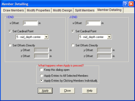
Figure 2.A: Member Detailing Tab in Graphical Member Modify (3D)
|
|
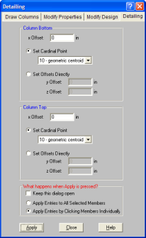
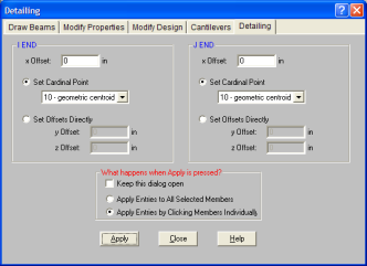
Figure 2.B: Column/Beam Detailing Tab in Graphical Member Modify (FLOOR)
A Detailing tab has been added to the double click dialog for the displaying and modification of the detailing info. The user can choose to Set y, z Offsets Using Cardinal Point or Set y, z Offsets Directly. When a cardinal point is picked, the value in the y Offset and z Offset text box will automatically be updated.
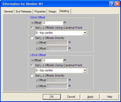
Figure 3: Detailing Tab in double click dialog
A detailing tab is available on the Members spreadsheet. The spreadsheet shows a label and 8 values for each member. The “I cardinal point” and “J Cardinal Point” are dropdown lists with numbers and a description. When a user picks a cardinal point, the y and z offset values will update automatically based on the current shape. When a new y and z offset are input by the user and it doesn’t fall on any cardinal point, the “Cardinal Point” will automatically change to “None”.
Note:
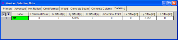
Figure 4.A: Detailing Tab in Member Spreadsheet(3D)
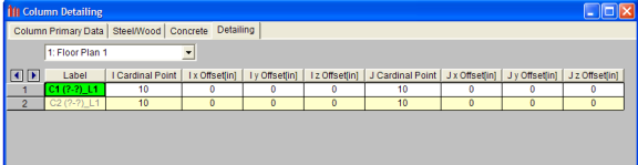
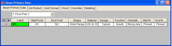
Figure 4.B: Beam/Column Detailing Tab in Member Spreadsheet(FLOOR)
Figure 5: Recalculate Detailing Offset button when Member Detailing Spreadsheet in Active
Figure 6: Detailing Info Checkbox in the Model Display Options Window
Note:
[.MEMBERS_DETAILING_DATA] data section is added to the .R3D file to hold the member true location data. [..RF_COLUMNS_DETAILING_DATA] and [..RF_BEAMS_DETAILING_DATA] data sections are added to the .RFL file to hold member true location data. The CIS2 translator is updated to read/write this new data section.